• Welcome Message

    Here are some neat circuits you might want to try. The schematics and printed circuit board patterns are GIF's, and may show up different on some browsers. You might want to save the images (especially the PC board patterns) to your hard drive, load them into a photo editor (Photoshop, Paint Shop Pro, The GIMP, etc.) and adjust the size before you transfer the pattern to a board. Printed circuit board patterns are available possible. This page is always under construction and there will be new additions from time to time. Some of these circuits were designed by me, most are not. Whenever possible I have tried to credit the author of a circuit but since many of these circuits are from my personal collection that I have gathered over a period of many years, this information is not always available. You can rank circuits according to how much you like a circuit by clicking on the lightning bolt icons. These ranks can be based on how much you like a circuit, whether a circuit worked or didn't work for you, or how useful you found a circuit. Additionally you can add your own comments at the bottom of each circuit by filling out the form.

LED Metronome Circuit

Posted by funny On 9:43 PM 0 comments

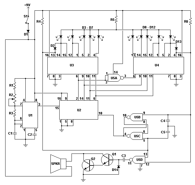
The LED Metronome is a modern interpretation of a classic device which is a staple of music teachers, students and composers everywhere. This circuit uses 12 LEDs to simulate the sweeping motion of the pendulum and a speaker with a simple amplifier to generate a tick as the LEDs at the end of the arc are struck. It is adjustable from about 40 BPM to just over 200 BPM. When made in a Lexan or Plexiglass case it can add a fun ultra-modern touch to music practice (though most music teachers agree that you should never rely on a metronome to keep your beat).

Schematic

Schematic for LED Metronome

Parts

Part
Total Qty.
Description
Substitutions
R1, R4, R6310K 1/4W Resistor
R211.5 Meg Linear Taper Pot
R31120K 1/4W Resistor
R51220 Ohm 1/4W Resistor
C1, C310.1uF Ceramic Disc Capacitor
C2, C4, C530.01uF Ceramic Disc Capacitor
D1, D2, D13, D1441N914 Signal Diode
D3-D1210Jumbo Red LED
Q1, Q222N3904 NPN Transistor
U11555 Timer IC
U214029 CMOS Up/Down Counter IC
U3, U424051 CMOS 8 Of 1 Switch IC
U514011 CMOS Quad 2 Input NAND Gate IC
SPKR1Small 8 Ohm Speaker
S11SPST Switch
MISC1Board, Wire, Case, Sockets for ICs, Battery holder, Knob for R2

Notes

  1. The circuit will reliably run from 6 to 12V. A typical 9V battery will be drained in several days by the LEDs with constant use. A 6V pack made from AA, C or D cells will last much longer.
  2. The circuit will need some calibration before use. Calibration is fairly easy and accomplished by using a stopwatch to count the number of beats. You'll want to calibrate for 60 BPM (one per second), 120 BPM (two per second) and 180 BPM (3 per second). Just use your stopwatch to find the points of R2 that correspond to those beat rates and the mark the dial appropriately. Next find 90, 150 and 210 BPM. By that time you should then be able to evenly mark the remaining positions on the scale.
  3. Blue LEDs need about 5V to light, so if you intend to use blue you will need to remove R5.
  4. For an ideal metronome effect, the LEDs should be arranged in an arc.
IR Remote Switch Circuit

Posted by funny On 9:37 PM 0 comments

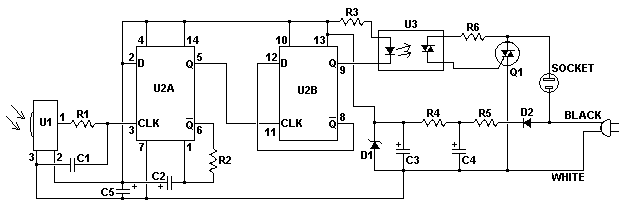
This circuit lets you control any line powered electrical device (a lamp, television, fan, etc.) using any infra-red remote control. Almost everyone these days has a pile of old IR remotes left over from appliances they have long ago disposed of them. With this circuit, you can put them back into use. The circuit looks for any modulated IR source and uses it to control a TRIAC, which then switches any appliance connected to it's socket. For example, you can use it to control the room lighting in your home theater setup using any of the remotes you already have. The circuit is powered using a simple transformerless power supply from the line itself, making it compact and easily built into a light switch, wall box, power bar or even the appliance you wish to control.
Schematic

Schematic of the IR Remote Switch

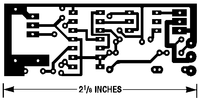
Printed Circuit Board Layout

PCB of the IR Remote Switch

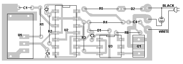
Printed Circuit Board Parts Placement

PCB parts placement of the IR Remote Switch

Parts

Part
Total Qty.
Description
Substitutions
R113 Meg 1/4W Resistor
R211.2 Meg 1/4W Resistor
R31680 Ohm 1/4W Resistor
R412K 1/4W Resistor
R514.7K 1/4W Resistor
R61150 Ohm 1/4W Resistor
C110.001uF Ceramic Disc Capacitor
C2, C521uF 50V Tantalum Electrolytic Capacitor
C3147uF 50V Tantalum Electrolytic Capacitor
C4110uF 50V Tantalum Electrolytic Capacitor
C51150 Ohm 1/4W Resistor
D111N4733 5V Zener Diode
D211N4003 Rectifier Diode
Q112N6071A TRIAC
U11GP1U52X IR Module
U21MC74HC74 D-Type Flip Flop
U31MOC3011 Opto Isolator
MISC1Board, Sockets For ICs, Mains Socket, Mains Plug and Cord, Wire

Notes

  1. Under normal circumstances, Q1 should not need a heatsink.
  2. The circuit is designed for a supply voltage of 120V.
  3. The printed circuit pattern is reproduced here larger then real life for clarity. It will need to be resized to the scale at the bottom of the image if you intend to transfer it to a board.
  4. The circuit functions as an on/off flip flop. Illuminate it with your remote once to turn it on, then again to turn it off.

IR Remote Extender Circuit

Posted by funny On 9:25 PM 0 comments

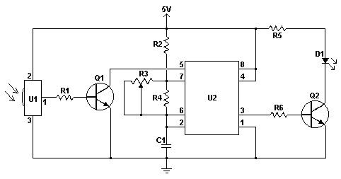
This IR remote extender can increase the range of most simple IR remotes (those operating on a 40KHz modulation) a significant distance. In use, the remote is pointed toward the detector on the circuit, and a button is pressed. The Sharp IR detector then decodes the 40KHz modulated signal into a series of pulses, which trigger a 555 timer. The 555 outputs pulses which are re-modulated and used to drive an IR LED. The circuit is excellent for use in a large room like a presentation hall where a typical IR remote is a bit weak. By extending the wires to the output LED (using shielded cable) you can control a device where line of sight isn't available (such as a wall full of TVs in another room).

Schematic


Schematic of the IR Remote Extender

Notes


  1. Only the CMOS TLC555 timer can be used in this circuit. The original NE555 cannot operate reliably at 40KHz. Acceptable substitutions are shown in the parts list.
  2. Almost all powerful IR LEDs can be used for D1 if the appropriate value of R5 is chosen.
  3. To calibrate the circuit, use a frequency counter. Connect it in parallel with D1 and then ground the base of Q1. Adjust R3 for 40KHz on the counter. If a counter is not available, you will just have to point a remote at the circuit, press a button, and then adjust R3 until it works. This can take a few tries as not all remotes transmit continuously.
  4. If you intend to remotely mount D1 any great distance, you will need to use shielded cable. Connect the shield to circuit ground.

Parts

Part
Total Qty.
Description
Substitutions
R1, R6210K 1/4W Resistor
R211K 1/4W Resistor
R3110K Linear Pot
R412.2K 1/4W Resistor
R5147 Ohm 1/4W Resistor
C110.01uF Ceramic Disc Capacitor
Q1, Q222N3904 NPN Transistor
D11IR LEDRadio Shack 276 143C
U11GP1U52X IR Module
U21TLC555 CMOS TimerLMC555, 7555
MISC1Board, Sockets For U2, Wire

Electronic Dice Circuit

Posted by funny On 9:17 PM 0 comments


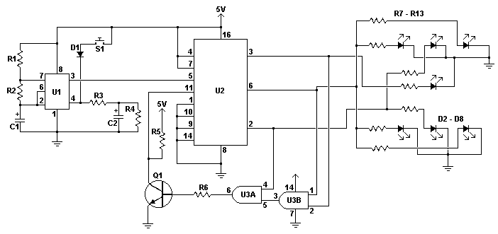
An electronic dice is a classic first project for those getting interested in electronics. A timer, counter and a few LEDs makes a circuit that can also add a new twist to some old boring board games. When the switch is pressed, a 555 timer in astable mode pulses a BCD counter which lights up a series of LEDs wired to mimic a dice. Two AND gates are used to reset the count back to one whenever the BCD output is seven. Thus, the circuit is not truly random but the natural bounce present in a pushbutton and the normal human ability to operate much slower then the oscillator make the output of the circuit seem random.

Schematic


http://www.aaroncake.net/Circuits/Electronic_Dice_Schematic.gif

Notes


  1. Pushing and holding S1 causes the LEDs to rapidly cycle. Releasing the button locks the pattern and shows a number from 1 to 6.
  2. When building the circuit, make sure to position the LEDs as shown on the schematic. Otherwise the pattern of the dice will look weird.
  3. Two circuits can of course be both powered by one switch to make a dual dice.

Parts

Part
Total Qty.
Description
Substitutions
R1, R5, R6322K 1/4W Resistor
R2110K 1/4W Resistor
R314.7K 1/4W Resistor
R41150K 1/4W Resistor
R7 - R137330 Ohm 1/4W Resistor
C111uF Electrolytic Capacitor
C214.7uF Electrolytic Capacitor
D111N4148 Signal Diode
D2 - D87Red/Green/Yellow LED
Q112N3904 NPN Transistor
U11555 Timer IC
U2174LS192 4 Bit Counter IC
U3174LS08 Quad Intengreted AND Gate IC
S11SPST Momentary Pushbutton Switch
MISC1Board, Wire, Sockets For ICs, Case

good

Posted by funny On 9:10 PM 1 comments

hello sad