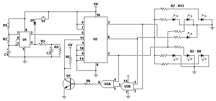
An electronic dice is a classic first project for those getting interested in electronics. A timer, counter and a few LEDs makes a circuit that can also add a new twist to some old boring board games. When the switch is pressed, a 555 timer in astable mode pulses a BCD counter which lights up a series of LEDs wired to mimic a dice. Two AND gates are used to reset the count back to one whenever the BCD output is seven. Thus, the circuit is not truly random but the natural bounce present in a pushbutton and the normal human ability to operate much slower then the oscillator make the output of the circuit seem random.
Schematic

Notes
- Pushing and holding S1 causes the LEDs to rapidly cycle. Releasing the button locks the pattern and shows a number from 1 to 6.
- When building the circuit, make sure to position the LEDs as shown on the schematic. Otherwise the pattern of the dice will look weird.
- Two circuits can of course be both powered by one switch to make a dual dice.
Parts
| Part | Total Qty. | Description | Substitutions |
| R1, R5, R6 | 3 | 22K 1/4W Resistor |
|
| R2 | 1 | 10K 1/4W Resistor |
|
| R3 | 1 | 4.7K 1/4W Resistor |
|
| R4 | 1 | 150K 1/4W Resistor |
|
| R7 - R13 | 7 | 330 Ohm 1/4W Resistor |
|
| C1 | 1 | 1uF Electrolytic Capacitor |
|
| C2 | 1 | 4.7uF Electrolytic Capacitor |
|
| D1 | 1 | 1N4148 Signal Diode |
|
| D2 - D8 | 7 | Red/Green/Yellow LED |
|
| Q1 | 1 | 2N3904 NPN Transistor |
|
| U1 | 1 | 555 Timer IC |
|
| U2 | 1 | 74LS192 4 Bit Counter IC |
|
| U3 | 1 | 74LS08 Quad Intengreted AND Gate IC |
|
| S1 | 1 | SPST Momentary Pushbutton Switch |
|
| MISC | 1 | Board, Wire, Sockets For ICs, Case |
|

0 Response for the "Electronic Dice Circuit"
Post a Comment